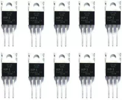
silicone 4028 IC CD4028BE Logic IC BCD to Decimal Decoder Interconnect Electronic Hobby Kit
Price: Not Available
Currently Unavailable
Highlights
- Power Source: DC
- Material: Plastic
- Weight: 55
Description
Sure, let's break down the CD4028BE Logic IC BCD to Decimal Decoder in detail, covering its full description and uses.
Full Description of the CD4028BE Logic IC BCD to Decimal Decoder
The CD4028BE is a CMOS (Complementary Metal-Oxide-Semiconductor) integrated circuit (IC) that functions as a BCD (Binary-Coded Decimal) to Decimal Decoder. It belongs to the CD4000 series of CMOS logic ICs, which are known for their low power consumption and wide operating voltage range.
* BCD to Decimal Conversion: This is its primary function. It takes a 4-bit binary input, which is interpreted as a BCD code (representing decimal digits 0 through 9). Based on this BCD input, it activates one of its ten output lines, corresponding to the decimal equivalent.
* Input and Output:
* Inputs (BCD): It has four input pins (A, B, C, D or often D1, D2, D4, D8, corresponding to the binary weights 2^0, 2^1, 2^2, 2^3 respectively). These inputs receive the 4-bit BCD code.
* Outputs (Decimal): It has ten output pins, labeled Q_0 through Q_9 (or O_0 through O_9). When a valid BCD input is applied, only the output pin corresponding to the decimal value of the BCD input will go HIGH (active-high output). All other nine outputs will remain LOW.
* Invalid BCD Inputs: If the 4-bit input code is greater than 9 (i.e., 1010 to 1111 in binary, which are not valid BCD for single digits), all ten output lines will remain LOW. This is an important safety feature to prevent spurious activations.
* Enable/Strobe Input (Optional/Not on 4028): Some decoders have an enable or strobe input to control when the decoding occurs. The CD4028 typically does not have a dedicated enable pin for its primary decoding function; it decodes continuously based on its inputs.
* Package Type: The "BE" suffix in CD4028BE specifically indicates a plastic Dual In-line Package (DIP). This is a common and easy-to-use through-hole package for integrated circuits, featuring two parallel rows of pins.
* CMOS Technology:
* Low Power Consumption: CMOS devices consume very little power, especially when they are in a static state (inputs are not changing). This makes them suitable for battery-operated devices.
* Wide Operating Voltage: CD4000 series ICs, including the CD4028, typically operate over a wide supply voltage range, often from 3V to 18V. This flexibility allows them to be integrated into various systems with different power supply requirements.
* High Noise Immunity: CMOS logic generally offers good noise immunity, meaning it is less susceptible to electrical noise interfering with its operation.
* Current Output (6.8 mA): This specification, often found in datasheets, refers to the typical output drive capability (sink or source current) for each output pin. It means that each output can typically supply or sink up to 6.8 mA of current to drive external loads like LEDs, small relays, or other logic gates.
Truth Table (Simplified Example):
| D (MSB) | C | B | A (LSB) | Q_0 | Q_1 | Q_2 | ... | Q_9 |
|---|---|---|---|---|---|---|---|---|
| 0 | 0 | 0 | 0 | HIGH | LOW | LOW | ... | LOW |
| 0 | 0 | 0 | 1 | LOW | HIGH | LOW | ... | LOW |
| 0 | 0 | 1 | 0 | LOW | LOW | HIGH | ... | LOW |
| ... | ... | ... | ... | ... | ... | ... | ... | ... |
| 1 | 0 | 0 | 1 | LOW | LOW | LOW | ... | HIGH |
| 1 | 0 | 1 | 0 | LOW | LOW | LOW | ... | LOW |
| (Invalid BCD inputs, e.g., 1010-1111) | LOW | LOW | LOW | ... | LOW | | | |
Uses and Applications
The CD4028BE is a fundamental building block in digital electronics and finds application in various areas, especially where BCD data needs to be converted for display or control:
* Digital Displays (Driving Individual Indicators):
* LED Indicators: It can directly drive 10 individual LEDs. For example, if you have a BCD counter and want to display its current state using 10 discrete LEDs (one for each digit 0-9), the CD4028 can be used. When the counter outputs "0011" (decimal 3), Q_3 goes high, illuminating the LED connected to Q_3.
* Lamp Drivers: Similar to LEDs, it can drive small indicator lamps.
* Seven-Segment Display Driving (Indirectly): While dedicated BCD to 7-segment decoders (like the CD4511 or 74LS47/48) are more common, the CD4028 can be used in a larger logic circuit to drive a 7-segment display. You would need additional logic gates (AND, OR gates) to combine the 10 decimal outputs into the correct segment patterns (a, b, c, d, e, f, g) for the 7-segment display. This method is more complex than using a dedicated decoder/driver but demonstrates its flexibility.
* Data Routing and Demultiplexing:
* The CD4028 can act as a 1-of-10 demultiplexer. If you connect a single data line to the common output side (or use an external gate), and use the BCD inputs as select lines, the data can be routed to one of the ten output channels.
* Control Systems:
* Event Sequencing: In simple control systems, a BCD input (perhaps from a counter or a switch matrix) could select one of ten different actions or
Read More
Specifications
In The Box
|
General
| Brand |
|
| Model Number |
|
| Skillset |
|
| Type |
|
| ROHS Complaint |
|
| Material |
|
| Age Group |
|
Dimensions
| Width |
|
| Height |
|
| Weight |
|
Power Features
| Battery Type |
|
| No Of Batteries |
|
| Battery Size |
|
| Power Source |
|
| Other Power Features |
|
Be the first to ask about this product
Safe and Secure Payments.Easy returns.100% Authentic products.
Back to top


